CE isn't a single number — it's a position in space
Most references to Center of Effort treat it as a point on a sail plan drawing.
SailrScience computes it as a three-dimensional position that moves with every
change in wind, sail selection, reef state, and heel angle.
How far forward or aft CE sits along the deck.
This is the axis that drives weather helm. Move CE forward
and the boat wants to bear away. Move it aft and you get helm pressure.
"Is my genoa pulling CE too far forward at this angle?"
How high CE sits above the waterline. Higher CE means more
heeling moment for the same force. Reefing lowers CE. A staysail
keeps CE low. This is the axis that governs comfort and control.
"How much does reefing the main actually lower CE?"
How far CE moves to leeward under heel. As the boat heels,
CE shifts laterally — increasing the moment arm and changing
the balance. This is the axis most sailors never think about.
Your sail’s measured planform. Not a lookup table.
Most models place CE from generic rig ratios. SailrScience starts from centroid
geometry — the measured planform of each sail — and models the center of
effort from that geometry, the active aero profile, trim state, and wind condition.
Tack, head, clew, plus roach profile when available. CE is a computed
force-application point, not a direct measurement of the flying sail.
A high-roach main puts CE higher and further aft. A deep-LP genoa moves it forward.
The geometry is traced back to sailmaker cut-sheet measurements, and the model
computes the force point from it. When you change sails in the model, CE moves
for the right reasons.
TPS, SPL, and IG are captured directly from your ORCi certificate — the exact
measurements that fix where each sail can fly. Forestay attachment, spinnaker pole
length, inner forestay position — these define the geometry of your sail plan.
SailrScience reads them, not assumes them.
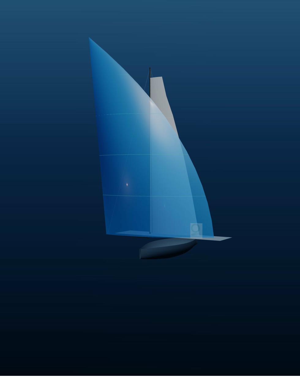
Actual Quantum Sails Mn-25 sail rendering in the live application
CE is one piece of the force balance (the solve that balances the aero and hydro forces at one wind condition — a SailEdge computation, never an ORC rating). See how drive, side force, heel, and depower all connect. The Physics →
Per-Sail and Combined
Every sail has a CE. Together they have one.
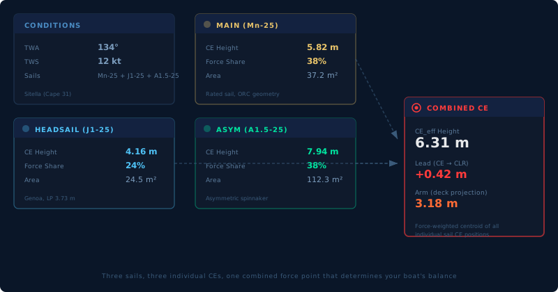
SailrScience computes CE individually for each sail — main, headsail, code sail —
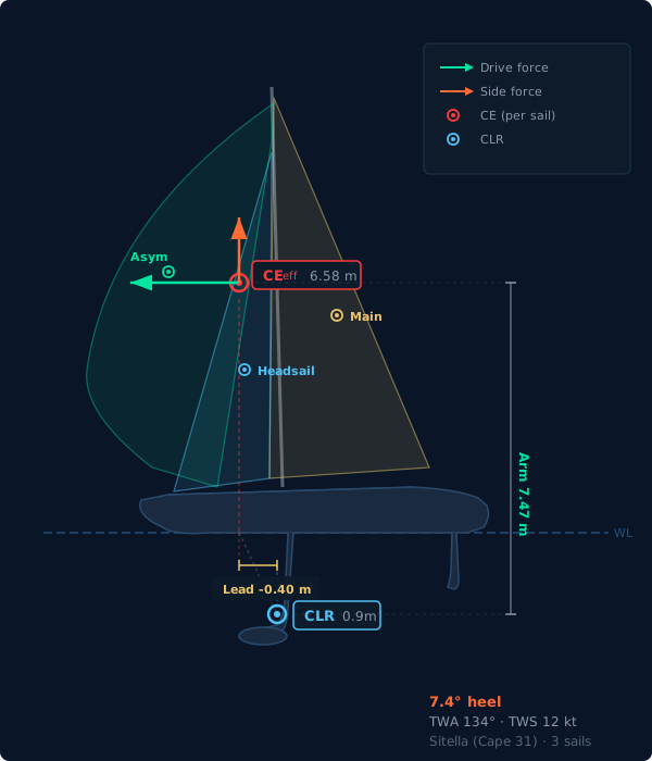
and then calculates the force-weighted combined CEeff that represents
where the total aerodynamic force acts on your boat. The combined CE marker points
straight down to the deck, showing you exactly where the resultant force meets
the hull. This is the number that matters for balance.
Sitella (Cape 31) broad reaching at TWA 134°, 12 kt — Main (Mn-25), Headsail (J1-25), Asymmetric (A1.5-25)
More area moves CE forward and higher. Your digital twin (the live performance model SailEdge builds from your ORC certificate — its certified dimensions, rig geometry and rated sail inventory) shows exactly where
CE lands with the new sail at every wind angle — before you spend the money.
Balance Problem
Why are we fighting the helm at 16 knots?
CE is too far aft, too high, or both. See CE position at 16 kt with your
current plan — and what happens when you switch to the jib, add a reef, or both.
Reef Timing
When does reefing actually pay off?
Reefing reduces area but lowers CE height, cutting heel moment. At some wind
speed, reduced heel gives back more than the lost area costs. CE shows you
where that crossover is.
Sail Loft — Design Iteration
How does this sail shape move CE across the wind range?
For sailmakers iterating on a design, CE tracks how planform changes shift
the force application point. Different roach, different LP, different CE
trajectory — visible across every regime.
The Full Picture
CE meets CLR — the balance that defines your boat
Center of Effort above the water. Center of Lateral Resistance below it. The
relationship between them determines whether your boat has weather helm, lee helm,
or neutral balance. SailrScience computes both — and shows you how every sail
change, reef, or furl shifts that balance.
When the mainsail blankets the headsail at deep angles, occlusion reduces
headsail lift and shifts the combined CE. The balance you see reflects sail
interaction, not just individual sail positions.
This is what experienced sailors feel. When they say "the boat feels
heavy" or "she's balanced beautifully," they're describing the CE—CLR relationship.
SailrScience makes that feel visible — the offset in meters, the heel it
drives, and how it changes with every puff and header. What took decades to develop
as instinct, your crew can now see on screen before leaving the dock.
CEeff — Above
The force-weighted center of all aerodynamic forces. Moves forward with bigger
headsails, moves up with more sail area, drops with reefs. The variable you
control through sail selection and trim.
CLR — Below
The center of all hydrodynamic resistance — keel, rudder, hull. Relatively fixed
by the boat’s design but shifts dynamically with boat speed and heel angle. The
anchor point that CE pushes against.
The horizontal distance between CE and CLR — the offset that creates helm.
CE ahead of CLR means lee helm. CE aft of CLR means weather helm. In sign
convention terms, positive Lead is forward (lee helm), negative is aft (weather
helm). A few tenths of a meter is the difference between a balanced boat and one
that fights you.
Heel Arm
The vertical distance from CE down to CLR — the lever that turns side force
into heeling moment. Higher CE, longer arm, more heel. Reef the main and the arm
shortens before the force drops. That’s why a first reef often feels like
free speed.
CE. CLR. RM. Every answer is a solved equilibrium.
CE is where the wind’s force acts. CLR is where the water pushes back. The third
force decides how much of that push your boat can stand up to: righting
moment — the stability envelope (the boat’s righting behavior — rated on the certificate, then computed by the R16 stability layer for each sailing state) built from hull form, ballast, and crew.
It has its own page in SailEdge — Boat
Tuning — but it belongs in this picture, because balance is never just CE and CLR.
Every number SailEdge reports is an equilibrium of these three forces: drive against
drag, heeling moment against righting moment, sail force against keel and rudder.
Change one — a reef, a heavier crew, a different headsail — and the other
two respond, and the equilibrium is re-solved. That solve runs across the 850,000+
physics evaluations (one full aero and hydro force-balance solve at one point of the wind envelope) behind your Edge Map (the performance delta grid — every sail measured against your boat’s ORC polar at every wind speed and angle). The balance you read on this page is computed
force physics, not a rule of thumb.
See where the forces balance →
What Balance Costs
Balance isn’t comfort. It’s speed you keep or give away.
A rudder held at angle to fight the helm is drag — all day, every leg. When CE
sits too far aft or too high for the conditions, helm load rises, rudder angle grows,
and the groove narrows: the band of headings where the boat is fast gets smaller, so
every small steering error costs more. Bring CE forward or down — a different
headsail, a reef, a flatter trim — and the same hull sails a wider groove with
less rudder drag.
CE working against you
Weather helm building, rudder angle climbing, drag rising with it. A narrow
groove that demands constant attention from the helm.
CE working for you
Helm near neutral, the rudder steering instead of correcting, a groove wide
enough to sail fast for hours. The boat is easier to sail — and faster
because of it.
These are not qualitative judgments. Lead in meters. Heel in degrees. Your digital
twin reports them for every sail plan you own, at every point of sail — CE meets
CLR, solved before you leave the dock. Balance is speed you keep or give away.
See the racer’s path →
Where This Leads
From force physics to the connected digital twin
The three-force system on this page — per-sail force and centroid computation
resolved into a combined center of effort, balanced against CLR and righting moment —
defines what your boat can do at every wind speed and angle. That physics foundation
is what the roadmap builds on.
The per-sail force and centroid computation presented on this page is SailEdge’s
patent-pending force physics — live in SailEdge today. The
roadmap’s Connected Digital Twin
describes where it leads. The portfolio’s IP story lives on the
SailrScience research page.